Table Of Content

For example, one direct method is to assume a candidate shape--perhaps from a database of previous designs--and make adjustments to the shape based on pressure calculations until the performance desired is obtained. There are also inverse methods where a target pressure distribution is defined and an objective function is created. Then, optimization methods can be applied until the actual and target are within some acceptable range of tolerance with each other. If you have ever seen the US Air Force Thunderbirds, shown in the figure above, you are aware of the amazing aerial maneuvers they perform. Planes that perform acrobatic flying like this are equipped with symmetrical airfoils. These airfoils have no camber, which means no difference in pressure and therefore no aerodynamic lift is created, as oncoming airstreams separate at the leading edge for purely horizontal or perpendicular flight.
A Complete Guide to Airfoil Shape Considerations
Notice the increase in the lift coefficient for a given angle of attack with increasing Mach number but to a point. The slower and aircraft flies, the higher the lift coefficient required to keep the aircraft in the air. Slower flying speeds result in a lower dynamic pressure and therefore a higher lift coefficient is required in order to produce sufficient lift equal to the aircraft weight. The maximum lift coefficient is produced just before the aircraft stalls; after which any increase in the angle of attack will reduced the lift produced and decrease drag. Any airfoil designed to have laminar flow for low drag must have a smooth skin. Any significant roughness or excrescences on the wing surface will trip the laminar boundary layer, causing it to become turbulent and greatly increasing drag.
Center of Pressure
Conceptually, defines how important viscous forces are with respect to the inertia of the flow. Here, density, , free-stream velocity, , a length scale (typically chord), , and dynamic viscosity, , all relate to this nondimensional number. Thus, using either of the two methods, it is shown that the pressure below the wing ishigher than the pressure above the wing. This pressure difference results in an upwardlifting force on the wing, allowing the airplane to fly in the air. As shown in Figure 4, the starting vortex rotates in a counter-clockwise direction.
Controlling Lift:
If you compare the C210 to the CH-750 you should immediately pick up that the Cessna airfoil is considerably thinner than that of the CH-750. The C210 makes use of a NACA 2412 airfoil at the root (later models used a NACA 64A-415) which is a fairly conventional airfoil profile with a maximum camber of 2% of the chord located at 40% of the chord. After reading the post on wing area and aspect ratio, you should appreciate that there exists a very clear relationship between the size (weight) of the aircraft and the size of the wing (wing area) required to operate the aircraft as intended. Flown at a high angle of attack, flat-bottomed wings are probably the simplest to make but can perform fairly poorly. First, let’s recall that a flow with Circulation is not the same as a flow with rotation.
They are typical of airfoil characteristics found in various standard catalogs, e.g., Abbott & Von Doenhoff. The results are often shown with respect to variations of the chord-based Reynolds number and/or the free-stream Mach number. Conversely, as the air above decompresses and joins with the air flowing from beneath the airfoil, lift decreases. In addition to the climbing required for takeoff, airfoil shapes for most aircraft must be designed to maintain elevation for long distances.
Today, it is possible to predict the aerodynamic characteristics of airfoils with a high confidence level using several popular computer codes, such as XFoil, which are freely available in the public domain. The classic approach to increasing the drag divergence Mach number is reducing wing thickness, i.e., thickness-to-chord ratio. However, this has several other disadvantages, including less fuel tank capacity and higher structural weight for the same strength and stiffness. Supercritical airfoils were initially studied in the 1950s by Herbert Pearcey at NPL in England and refined during the 1960s by Richard Whitcomb at NACA. Today, supercritical airfoils are used on nearly all commercial jet aircraft, allowing them to cruise at higher flight Mach numbers between 08 and 0.85.
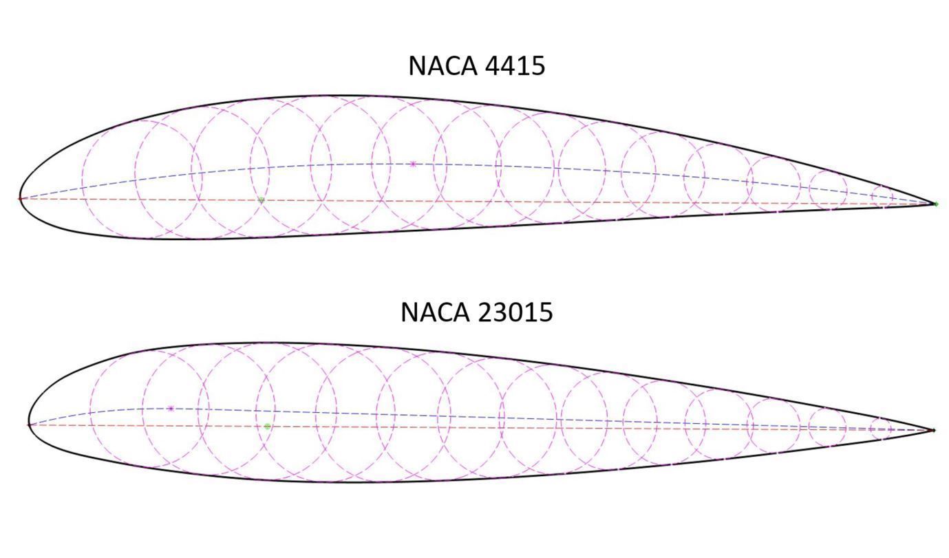
NACA Method of Drawing Airfoil Shapes
A representative pressure coefficient distribution around an airfoil in transonic flow is shown in the figure below. Notice in this case that the region of supersonic flow over the leading edge region produces a more uniform low pressure terminated by an abrupt pressure recovery, a classic signature indicative of the presence of a shock wave. This outcome contrasts with the subsonic flow, where the lowest pressure value is much closer to the leading edge, giving an adverse pressure gradient over most of the chord. The steep adverse pressure gradient near the shock wave makes the boundary layer much more prone to local thickening and often produces flow separation, i.e., the onset of shock-induced separation.
Connection to Aerodynamic Characteristics
Rotational flows are described by viscous forces and imply the fluid elements rotate, see for example this link. In the later example in the link are two flows that both have circulation (as the flows rotate like a tornado, hurricane, or vortex), but only one is rotational (where the fluid elements themselves rotate). Circulation is a feature relevant to vortices, and via Kutta-Jukowski, is why line-vortices are critical for lift generaton in potential flow.

Deep learning based multistage method for inverse design of supercritical airfoil - ScienceDirect.com
Deep learning based multistage method for inverse design of supercritical airfoil.
Posted: Thu, 16 Sep 2021 20:23:25 GMT [source]
For airfoils with small camber, i.e., small values of surface slope angle , applying the thickness along the axis is a reasonable approximation. Caution should also be exercised to ensure the correct signs (positive or negative) are used. Still, there are exceptions, especially for airfoils with large thickness-to-chord ratios or large amounts of nose camber. The validity of the Glauert rule generally extends up to the critical Mach number for the airfoil section, , i.e., the onset of supercritical flow.
This work led to organizing the results into families of airfoils known to produce specific aerodynamic characteristics. With a catalog of airfoils with measured aerodynamic characteristics, aircraft designers could quickly choose the most appropriate airfoil profile for their particular application. Sir George Cayley, often revered as the “Father of Aeronautics,” delineated the problem of sustentation, i.e., aerodynamic lift, from that of drag, i.e., the component of aerodynamic resistance. Cayley obtained the profile shown in the drawing below by measuring the cross-sectional shape of a trout, which, interestingly enough, conforms closely to modern low-drag “laminar” airfoil sections. Historically, the most suitable airfoils for most practical engineering applications were obtained through an evolutionary process.
Design and experiment of concentrated flexibility-based variable camber morphing wing - ScienceDirect.com
Design and experiment of concentrated flexibility-based variable camber morphing wing.
Posted: Tue, 25 May 2021 19:31:14 GMT [source]
In addition, the leading-edge shape of the airfoil is often defined geometrically in terms of a nose radius, which also affects the airfoil’s aerodynamic characteristics. The problem of defining the airfoil pressure distribution for an airfoil with thickness and arbitrary shape was tackled by Theodorsen & Garrick in the early 1930s. The design of practical airfoil profiles was further aided by methods such as the conformal transformation first developed by Prandtl & Tietjens. This latter approach made it possible to compute pressure distributions and the resulting lift and pitching moment characteristics of some specially shaped “Joukowski” airfoils. The aerodynamic properties of Joukowski airfoils were measured in wind tunnel tests starting in the late 1920s at Gottingen in Germany and by the NACA in the U.S.A. from 1930 onward.
While dimensional values forces (lb or N) and moments (ft-lb or N-m) are helpful in many forms of analysis, it is far more convenient to work with non-dimensional aerodynamic quantities, such as lift and drag coefficients. “NACA airfoils are mid-loaded,” he explained, meaning the lift is evenly distributed across the chord, which leaves the front end susceptible to airflow separation at high angles of attack. As a result, the NACA airfoils “have an unnecessarily high see-sub-m.” The initial camber angle at the nose of the NACA airfoils contributes to airflow separation and, consequently, the high pitching moments. To correct this problem, Riblett moved the loading forward and changed the initial camber angle to 12 degrees. As a result, all of his airfoils are soft-stall airfoils and there is no leading edge separation at high angles of attack. This latter goal is achieved using camberlines that produce a more uniform pressure loading from the leading edge to a distance .


No comments:
Post a Comment