Table Of Content

The CLMAX of the wing in takeoff configuration and the wing loading define the stall speed in that configuration. That stall speed in turn is one of the major parameters determining takeoff distance. It’s rare that takeoff distance sizes the wing, particularly if the wing is sized to meet stall speed requirements in landing configuration, but it does happen, particularly for an airplane with a purely cruise-optimized wing. The airfoil characteristics will still come into play because the flaps are rarely full span and because flaps tend to produce a constant increment in max lift. That said, the CLMAX value that counts is for the wing with the flaps down, and that is what should be used to evaluate the wing’s maximum lift and set wing loading. The first step is to determine the lift coefficient (CL) of the wing at cruise conditions.
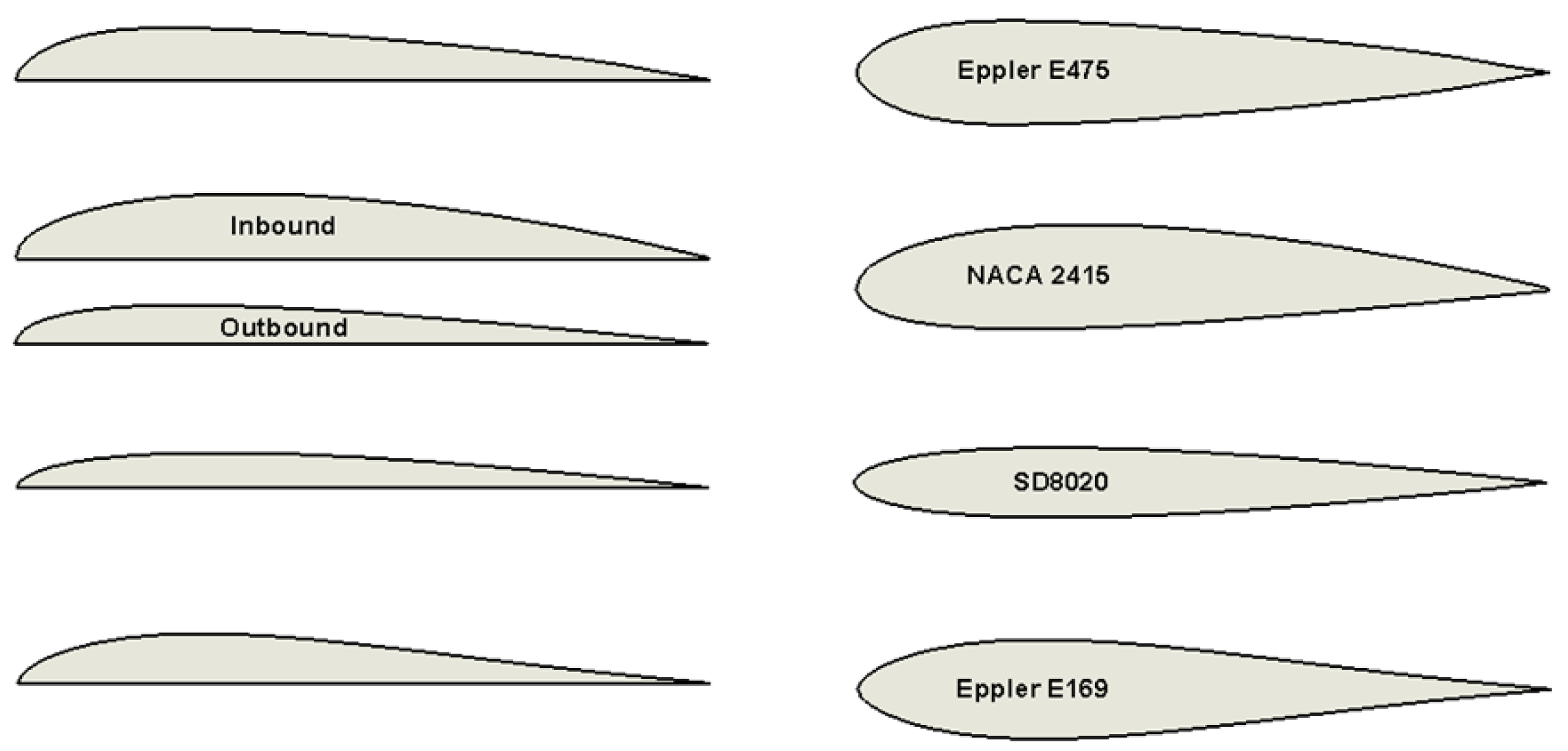
Symmetrical Airfoils and Their Applications
Let’s look at all three airfoils next to one another before diving into the airfoil engineering principles used to select each one for the aircraft considered. Let’s break down the main categories to give you a better idea of which airfoil is right for your airplane. Riblett’s book—GA Airfoils—represents a lifetime worth of work improving and tweaking the NACA airfoils. You can tell a creative mind by its doodles—and Riblett thought much about aircraft design.
Sling High Wing
Even with these attributes, symmetrical wings are far less common than non-symmetrical or cambered airfoils. A significant problem with thin supersonic airfoils is that at low (subsonic) flow flight speeds, they tend to produce leading-edge flow separation and stall even at moderate angles of attack. Therefore, many aircraft that employ supersonic airfoils must use high-lift devices for takeoff and landing, such as large leading-edge slats along the entire wing. Another method is drooping the leading edge using camber, which maintains the supersonic performance while markedly improving low-speed characteristics. Nevertheless, supersonic aircraft have relatively high takeoff and landing speeds and may need drogue parachutes to reduce their landing distances. As the angle of attack increases further, the boundary layer thickens, and the aerodynamic characteristics start to become non-linear with respect to the angle of attack.
Center of Pressure
Therefore, it is possible to mimic two-dimensional wings theoretically and experimentally, deriving a better understanding of the aerodynamics of the airfoil section by itself. Comparing this airfoil to the modified NACA of the CH-705 reveals a profile that produces less drag as it's thinner and more streamlined. The airfoil is also less cambered than the NACA which means it produces less lift for a given angle of attack when compared to the CH-750 airfoil. This results in a longer takeoff run as the aircraft needs to be at a higher speed to produce sufficient lift to get airborne.
Invertible neural network tool helps optimize airfoil design - Tech Xplore
Invertible neural network tool helps optimize airfoil design.
Posted: Thu, 26 Oct 2023 07:00:00 GMT [source]
While the preceding flow visualization images are interesting and of much value, the resulting forces and moments on the airfoil are also important. The effects of the Mach number and, hence, the compressibility of the flow on the lift curve are shown in the figure below. Typically, flow with a Mach number lower than 0.3 is considered incompressible, and an airfoil will have a lift-curve slope of about per radian or 0.11 per degree. Nevertheless, it can be seen that the lift-curve slope increases quickly at the higher Mach numbers because of the effects of compressibility. Notice also that the maximum lift of the airfoil decreases with increasing Mach number.
A reinforcement learning approach to airfoil shape optimization Scientific Reports - Nature.com
A reinforcement learning approach to airfoil shape optimization Scientific Reports.
Posted: Fri, 16 Jun 2023 07:00:00 GMT [source]
Maximum lift, pitch moment, drag coefficient, and even airfoil dimensions are changed with just a mouse click and drag. As with landing, it is important to do the evaluation with the flaps in the proper configuration. Most single-engine airplanes take off with the flaps up because they have acceptable takeoff distance and lower drag in this configuration. Regulations vary, so the stall speed must be evaluated in the proper configuration. For example, in the U.S., a single-engine airplane certified under FAR Part 23 is required to have a stall speed no greater than 61 knots in the landing configuration. Landing configuration in this context can include deflected flaps or other high-lift devices.
Often, the moment curve has a shallow positive slope because the aerodynamic center (defined later) is close to but just forward of the 1/4-chord. It should be appreciated that the flow over any wing of finite span will be inherently three-dimensional and further complicated by the effects of the vortices that trail behind the wing, as shown in the figure below. The presence of these vortices produces a downwash flow over the wing, affecting the local angles of attack over the entire wing and, therefore, its lift and overall aerodynamic characteristics. The flow can be assumed nominally two-dimensional only at sections well away from the wing tip vortices. What the graph does show though is that the F-16 is most efficient at high speeds where the lift coefficient is low (high speeds).
Drag Characteristics
The subscripts 1 and 2 indicate different points along the same streamlineof fluid flow. The following presents two of several ways to show that there is a lower pressure abovethe wing than below. Where would be the number of points on the upper surface and would be the number of points on the lower surface, the idea being shown in the figure below. The process can also be performed in MATLAB by using the polyfit function. The linear least-squares method is a numerical process of finding a straight line that best represents the trends shown in a particular data set.
This would result in poor low speed flying characteristics (high stall speed and long takeoff roll) if this wing profile was used on either the C210 or CH-750. However this is not a problem for the F-16 as it is designed to operate at high speed and its powerful jet engine allows it to accelerate quickly to the required takeoff speed during departure. The thickness of the airfoil is a very important design parameter and as always expressed as a percentage of the total chord.
Tosatisfy the conservation of angular momentum, there must be an equivalent motion to opposethe vortex movement. The velocity vectors from this counter circulation add to the free flow velocityvectors, thus resulting in a higher velocity above the wing and a lower velocity below thewing (see Figure 6). This latter result shows that the lift-curve slope is lower in supersonic than subsonic flight and decreases with increasing Mach number. In many aerodynamic applications, the 1/4-chord point is used as a reference point, i.e., . The 1/4-chord has theoretical significance, this being the aerodynamic center for a thin airfoil in an incompressible flow. However, even if another reference point were selected, converting from one reference point to another is easy because it is just the application of the rules of statics, as shown in the figure below.
The variation of the drag with the angle of attack and/or with the lift coefficient is of great interest because of its essential effects on aircraft performance, i.e., the drag generally always acts to diminish the aircraft’s performance. Some representative results are shown in the figure below in terms of drag coefficient versus lift coefficient for both a conventional airfoil (in this case, the NACA 23012) and a so-called “laminar flow” airfoil (a NACA 63-series airfoil). The drag stays low until the angle of attack and the corresponding lift coefficient have increased to the point that significant boundary layer thickening occurs. Pitching moments are defined as positive when the moment tends to increase the angle of attack of the airfoil section, i.e., positive pitching moments are equivalent to nose-up moments.


No comments:
Post a Comment